To complete each control step for a possible failure mode, as described in the previous article,
gear-specific material data is required. This data is obtained by dedicated gear testing
methods. Currently there are no standardized test procedures available, which could be
employed to generate this data. However the VDI 2736:Part 4 [1] which provides comprehensive
recommendations for the testing methodology.
Test samples
As by the guideline, three gear geometries are proposed for experimental characterization. Being
closest to the majority of practical applications with plastic gears, the Size 1 geometry is most
commonly used for testing. The lack of standardization results in several other gear geometries
being dealt with in scientific and technical reports. It is however extremely important for the
development of future plastic gear rating standards that the test sample geometries are unified in a
similar manner as in the vast majority of comparable standards dedicated to characterization of
material's mechanical properties.
Parameter |
Nomenclature |
Unit |
Size 1 |
Size 2 |
Size 3 |
Type of gear |
/ |
/ |
spur gear |
spur gear |
spur gear |
Centre distance |
a |
mm |
28 |
60 |
91.5 |
Normal module |
mn |
mm |
1 |
2 |
4.5 |
Number of teeth |
z1 1/z2 |
/ |
17/39 |
30/30 |
16/24 |
Gear's facewidth |
b1/b2 |
mm |
8/6 |
13/12 |
22/20 |
Pressure angle |
αn |
° |
20 |
20 |
20 |
Tip diameter |
da1max/da1min |
mm |
19.40/19.35 |
64.916/64.779 |
82.45/82.36 |
da2max/da2min |
mm |
40.40/40.30 |
63.098/62.902 |
118.35/118.26 |
Root diameter |
df1max/df1min |
mm |
14.902/14.610 |
55.916/55.779 |
61.917/61.215 |
df2max/df2min |
mm |
35.866/35.691 |
54.498/54.301 |
97.824/97.122 |
Sample quality
The gear's manufacturing quality affects the stress-state in the gear when under load [2]. Controlling the test samples production quality is utmost important for a reliable comparison of test data. The gear manufacturing quality is usually evaluated according the ISO 1328 [3]. For material characterization purposes, gears with the majority of rating parameters in quality 10 (or better) are recommended for testing.
Besides the gear's geometrical quality, even more important is that the gears are produced without any significant weld lines and without voids. If during gear testing, the failure occurs on the weld line or at a void location the test result is not a function of a material property but rather of the defect in the gear as a result of a bad quality sample production. Since the gear tests are used to generate gear-specific data on the material properties the failure should be a single function of the material's performance.
Test benches
There are three main test rig layouts used for gear testing. The back-to-back test rig is a very well-known concept which has been widely used for testing of steel gears. For testing of plastic gears, the basic concept of this test rig has some limitations. In a back-to-back test rig, the torque on the tested gear pair is applied by a rotational displacement of a loading clutch. Plastic gears deflect under load significantly more than steel ones. Due to the teeth deflection, some of the torque applied with a rotational displacement of the loading clutch is lost.
Additional torque loss occurs during the test duration due to the viscous properties of plastic materials and additional deflection of teeth due to creep. As plastic gears wear quite significantly during operation, another portion of torque loss occurs due to tooth wear. This problem can be solved by applying a continuously adjustable electromechanical or hydraulic torque application system, which however significantly complicates the test rig's design and control, adding to overall cost of the test rig. Another disadvantage when it comes to gear testing is that the center distance is fixed and determined by the master gear pair.
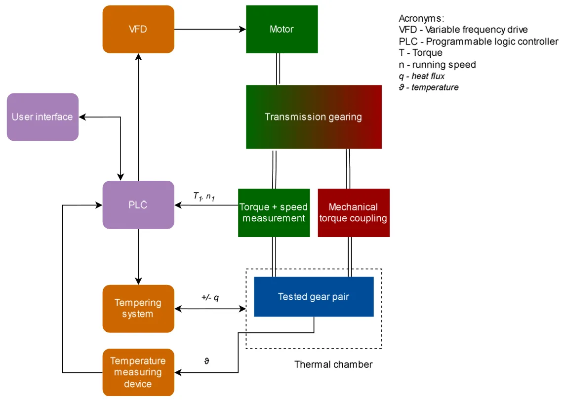
Fig. 1: Schematic representation of a closed-loop, back-to-back gear test rig.
Another possible test bench layout is a mechanically open loop system, where on one side, the motion and power are applied by a motor and on the braking shaft, the braking torque is usually applied by employing a brake or a generator. Such a test rig concept allows for a continuously adjustable center distance, enabling testing of several different gear geometries. By controlling the torque and speed on both sides, the load applied on the tested gear pair can be very accurately controlled.
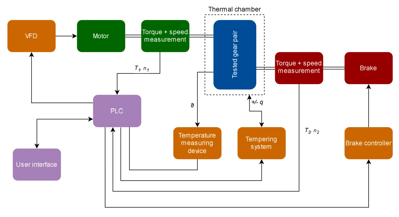
Fig. 2: Schematic representation of an open-loop test bench.
Additionally, the open-loop type test rig can be formed of a pair of electric motors where one provides the input driving torque to the pinion, while the other acts as a brake on the driven side. The drive and brake shafts can be positioned in parallel one next to the other in which case the motors have to be connected to both shafts via belts or chain transmissions.
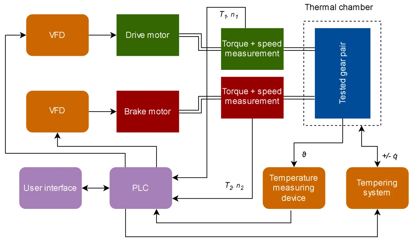
Fig. 3: Schematic representation of an open-loop test rig with parallel driving/braking motor configuration.
The fourth possible layout is the pulsator test rig, also called a single tooth bending test machine. In this type of test rig, a single tooth is subjected to pulsating cyclic loading in the tangential direction relative to the gear tooth. The limitation of the test rig is that it can only be employed to study root fatigue, while other possible failure modes e.g. wear, pitting or thermal overload cannot be observed. Another limitation is that the load on the tooth is not applied in exactly the same direction as when gears are meshing, requiring a suitable analytical model to correlate the results with gear meshing conditions.
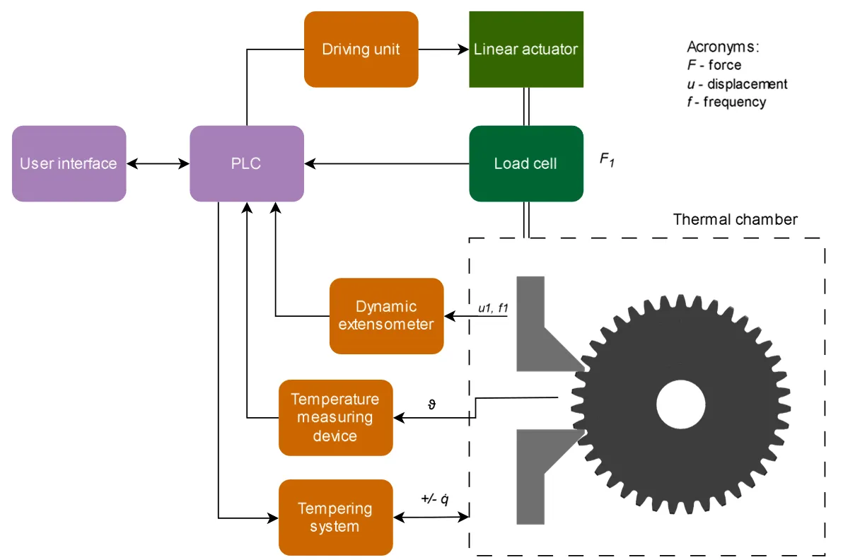
Fig. 4: Schematic representation of a pulsator test rig.
Irrespective of the test rig design, the most important testing conditions, i.e. the transferred torque, the plastic gear's temperature and the rotational speed needs to be precisely controlled during the entire test. While torque and speed control can be quite easily achieved, controlling the plastic gear's temperature is a bit more challenging.
Tests conducted for S-N curve generation are usually performed at a selected rotational speed and at various torque levels. The rate of heat generation and the resulting temperature rise depend strongly on the transmitted torque. A sophisticated gear-temperature control system is therefore required to control the plastic gear's temperature at a selected level, irrespective of the tested torque and rotational speed.
The increase in gear temperature significantly impacts the durability and fatigue resistance of polymer gear pairs. S-N curves, which chart stress against the number of cycles to failure, have to be assessed as a function of temperature. Typically, these curves are characterized as a function of bulk root temperature. However, as seen in Fig. 13, the choice of measurement point greatly affects the results. The images depict a gear test conducted under controlled conditions (with a temperature set at 90°C), selecting three different points for measurement. These varying points can yield substantially different outcomes.
The VDI 2736 offers general instructions for measuring root temperatures, yet a more precise specification is advisable. It is recommended to place the measurement sensor at the midpoint of the gear's face width and on the passive flank side. This location typically provides an average temperature that accurately reflects the root temperature, given that the passive tooth flank does not heat up substantially compared to the root temperature, and it will therefore influence the measurement only marginally. Conversely, placing the sensor on the side surface beneath the root tends to produce significantly lower temperature readings compared to those at the center of the face width.
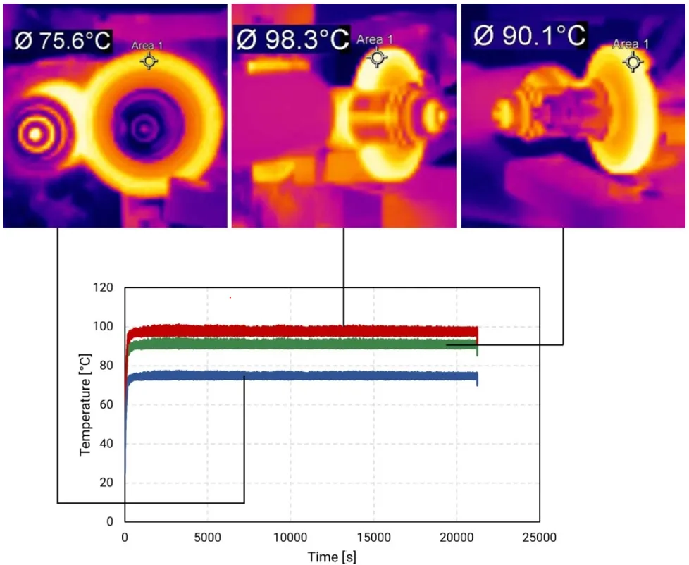
Fig. 5: Controlled operating temperature of a plastic gear - influence of the measurement location on the measured temperature.
References
[1] VDI 2736: Blatt 4, Thermoplastische Zahnräder, Ermittlung von Tragfähigkeitskennwerten an Zahnrädern, (2014).
[2] D. Zorko, Effect of Process Parameters on the Crystallinity and Geometric Quality of Injection Molded Polymer Gears and the Resulting Stress State during Gear Operation, Polymers 15 (2023) 4118. https://doi.org/10.3390/polym15204118.
[3] ISO 1328-1:2013: Cylindrical gears - ISO system of flank tolerance classification - Part 1: Definitions and allowable values of deviations relevant to flanks of gear teeth, (2013).